CONTACT
Focus Ion Beam
- Introduction to the Principle of Focused Ion Beam
-
A Focused Ion Beam system is a device that scans a focused ion beam across the surface of a specimen and detects secondary electrons generated from the specimen to observe microscopic images or process the specimen surface.
A Focused Ion Beam system has a configuration and functions similar to those of a Scanning Electron Microscope (SEM).
First, we will introduce the basic principle of a scanning electron microscope.
However, there are several important differences between a Scanning Electron Microscope and a Focused Ion Beam system.
Based on these differences, we will introduce the key features of the Focused Ion Beam system.
Scanning Electron Microscope Overview
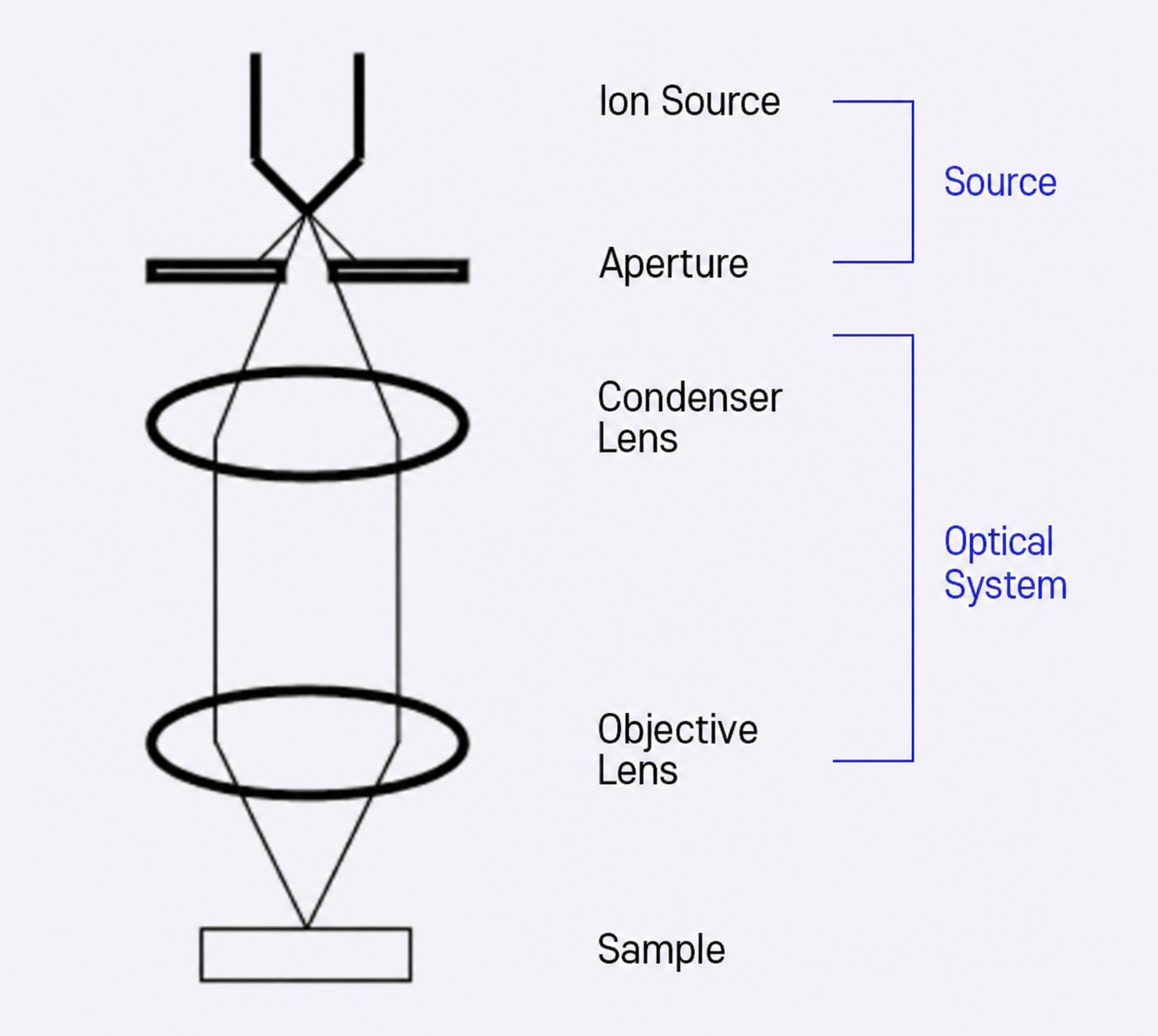
Figure 1 - Conceptual Diagram
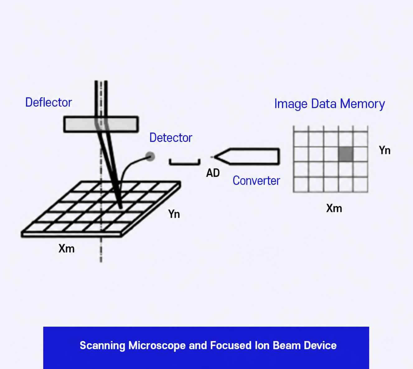
Figure 2 - Scanning Microscope
Light emitted from the source is collected through an aperture or a condenser lens (also referred to as CL) to form a beam.
The beam is then focused onto the specimen surface by an objective lens (also referred to as OL).
The focused beam is scanned across the sample surface using a deflector.
Secondary signals generated from the specimen surface by beam irradiation are detected by a detector, and the corresponding data are stored in image memory according to the coordinates of the beam irradiation position.
The data stored in the image memory are displayed on a computer screen, allowing the microscopic image of the irradiated area to be observed.
Beam Source
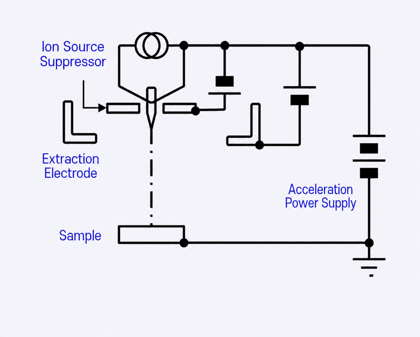
Figure 3 - Ion Source Conceptual Diagram
The source from which the beam is generated is generally referred to as the beam source.
In a Scanning Electron Microscope (SEM), it is commonly called an Electron Gun, while in a Focused Ion Beam (FIB) system, it is generally referred to as an Ion Gun or Ion Source.
An electric field is applied between the sharp tip of a metal emitter and an extraction electrode to extract charged particles.
The extracted particles are accelerated by the voltage supplied from the acceleration power source and directed toward the specimen.
In the case of an Ion Gun, liquid gallium (Ga) is supplied to the sharp metal tip and emitted by the force of the electric field.
An accelerating voltage of approximately +5 kV to +30 kV is commonly used.
A higher accelerating voltage makes it possible to produce a finer beam.
However, since a higher accelerating voltage can also cause greater damage to the specimen, 30 kV is commonly used as an appropriate operating condition for observation.
Beam Optics
Charged particles generated from the beam source are focused using a magnetic or electric field and directed onto the specimen surface for scanning.
In a Scanning Electron Microscope (SEM), the beam is generally controlled using the magnetic field generated by electromagnetic lenses.
This method makes it possible to achieve relatively high performance at a reasonable cost because the current-control circuitry for the electromagnets is less susceptible to external noise, and the electromagnets do not need to be installed inside the vacuum chamber.
In a Focused Ion Beam (FIB) system, however, magnetic-field control is generally not used. In a magnetic field, the trajectory of charged particles varies depending on their mass.
Since an ion beam may contain ions of different masses, such as isotopes, it is difficult to focus the beam accurately using a magnetic field.
Therefore, an electric field is used instead. When an electric field is used, a high voltage must be applied to electrodes installed inside the vacuum chamber.
The system must also be designed to prevent electrical discharge even under high-voltage operation.
In addition, voltage-control circuits are generally more susceptible to noise than current-control circuits, so appropriate noise-reduction measures are required.
The performance is also strongly affected by the mechanical positioning of the electrodes. To achieve high performance, components must be assembled with micron-level precision.
SIINT has overcome these technical challenges and successfully commercialized Focused Ion Beam systems.
- EElectron Beam and Focused Ion Beam
-
In a Scanning Electron Microscope (SEM), an electron beam is irradiated onto the sample, while in a Focused Ion Beam (FIB) system, a gallium (Ga) ion beam is used.
When an electron beam is irradiated onto the surface of a specimen, secondary electrons are emitted from the specimen surface.
These secondary electrons are generated when the energy of the incident electrons causes electrons in the specimen to leave their original trajectories and be emitted from the surface.
As the accelerating voltage of the electron beam increases, characteristic X-rays are generated depending on the material.
The amount of secondary electron emission varies according to the surface topography and material properties.
By obtaining the two-dimensional distribution of the emitted secondary electrons, a microscopic image of the specimen surface can be observed.
By analyzing the wavelength distribution, or spectrum, of the characteristic X-rays, the elemental composition of the specimen surface can be identified.
In addition, by obtaining a two-dimensional distribution of specific X-rays, the spatial distribution of particular materials can also be observed.
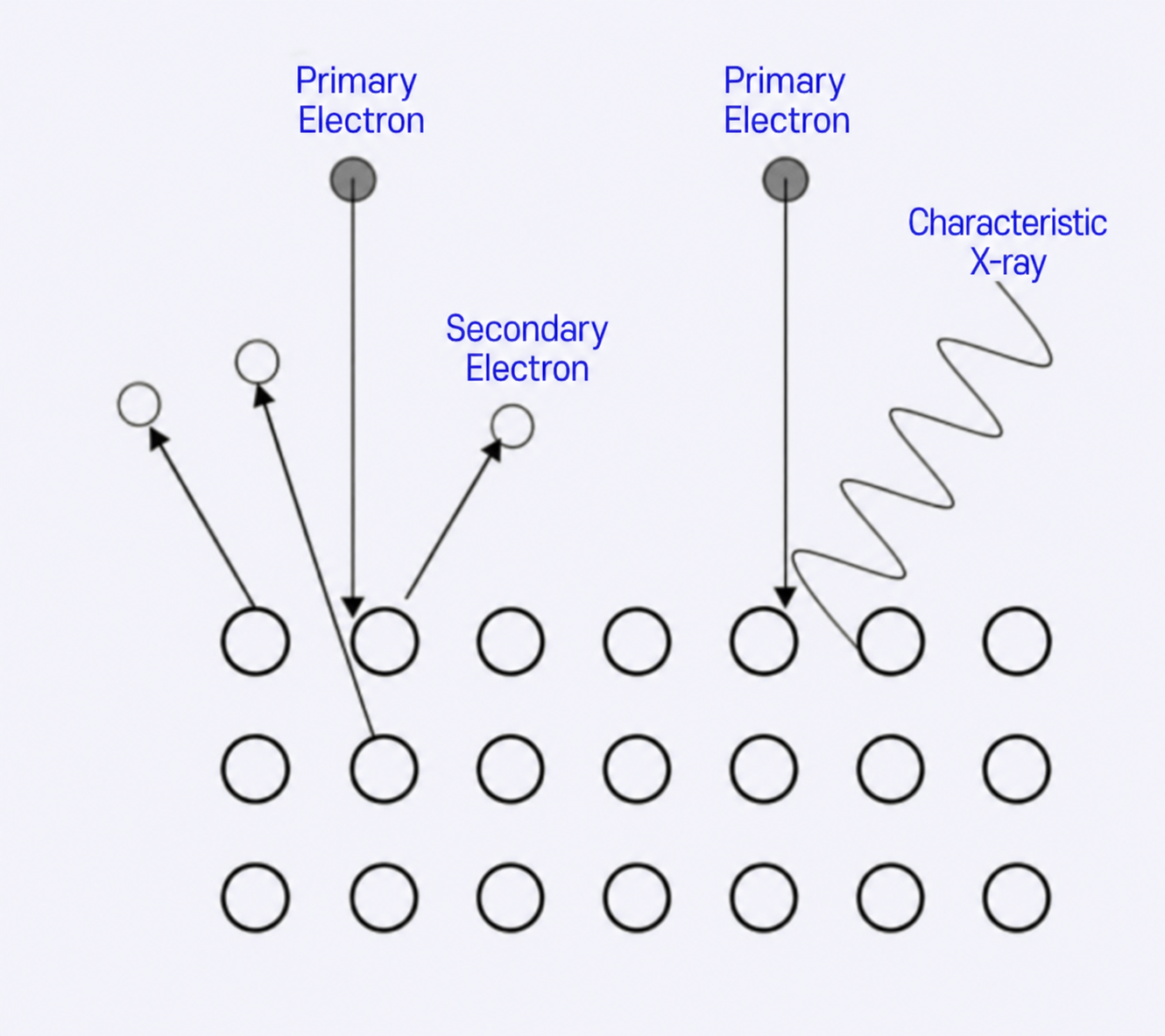
Figure 4 - Electron Beam Irradiation
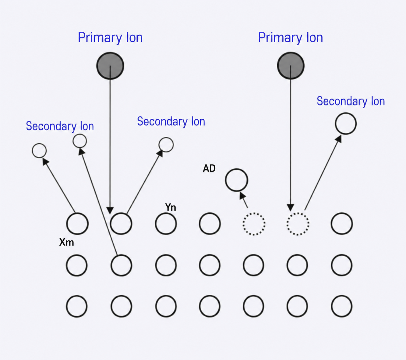
Figure 5 - Ion Beam Irradiation
When an ion beam is irradiated onto the sample surface, secondary electrons are emitted from the surface in the same manner as with an electron beam.
As with an electron beam, a microscopic image of the sample surface can be obtained by measuring the two-dimensional distribution of these secondary electrons.
In addition, because gallium (Ga) ions are much heavier than electrons, a sputtering phenomenon occurs in which atoms composing the sample are ejected from the surface.
The secondary ions generated during this process can be detected, and their two-dimensional distribution can also be used to observe a microscopic image of the sample surface.
In general, the relationship between the spatial resolution and material dependence of these secondary signals is as follows.
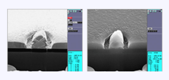
Figure 6 - Secondary Electron Image Comparison
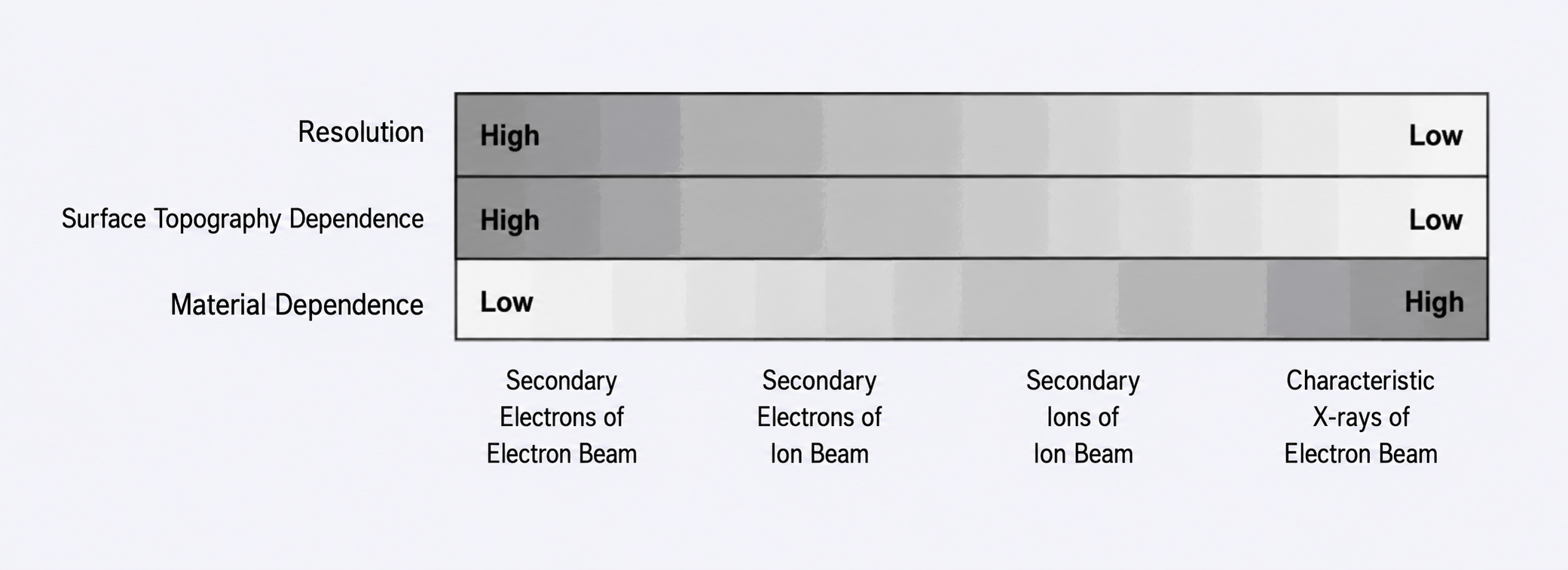
Figure 7 - Characteristics Comparison
Focused Ion Beam Processing
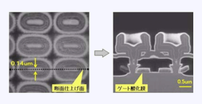
Figure 8 - 64M-DRAM Cross-Section Processing Observation
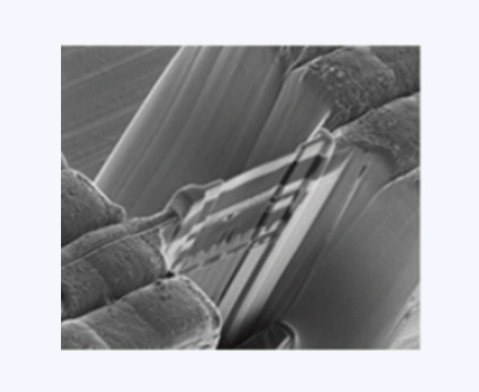
Figure 9 - TEM sample Fabrication
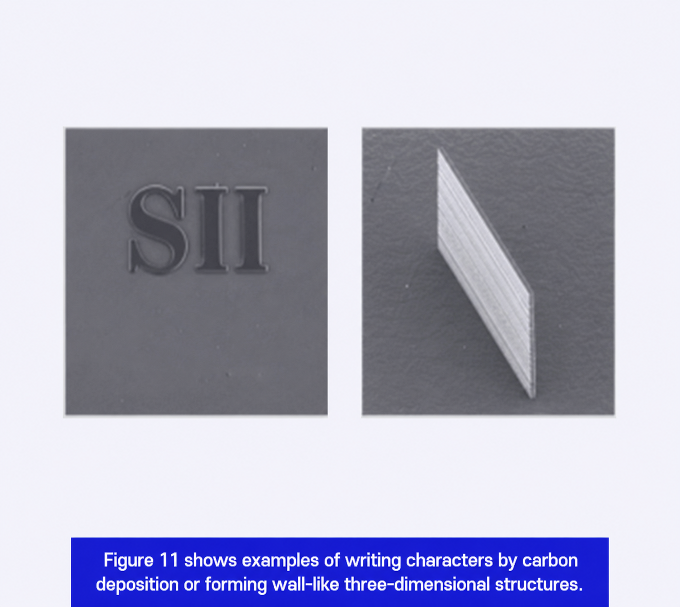
Unlike an electron beam, an ion beam can be used to directly process the sample surface.
Etching
As introduced earlier, sputtering occurs when an ion beam is irradiated onto the sample surface.
By increasing the ion beam dose, the amount of material removed through sputtering increases, making it possible to etch the sample surface.
By applying this technique, a specific area of the sample can be etched to expose a cross-section for cross-sectional observation. It can also be used for TEM sample preparation, in which a thin specimen is extracted from a specific area of the sample.
Deposition
When a primary ion beam is irradiated onto the sample, secondary electrons are generated.
These secondary electrons contribute to the decomposition of the precursor gas, separating it into gaseous and solid components.
The gaseous components are removed through the vacuum exhaust system, while the solid components are deposited on the sample surface.
Using this phenomenon, selective mask deposition can be performed only in the area irradiated by the ion beam.
SIINT has developed and commercialized a precursor gas supply system that efficiently delivers the deposition source gas to the vicinity of the ion beam irradiation area.
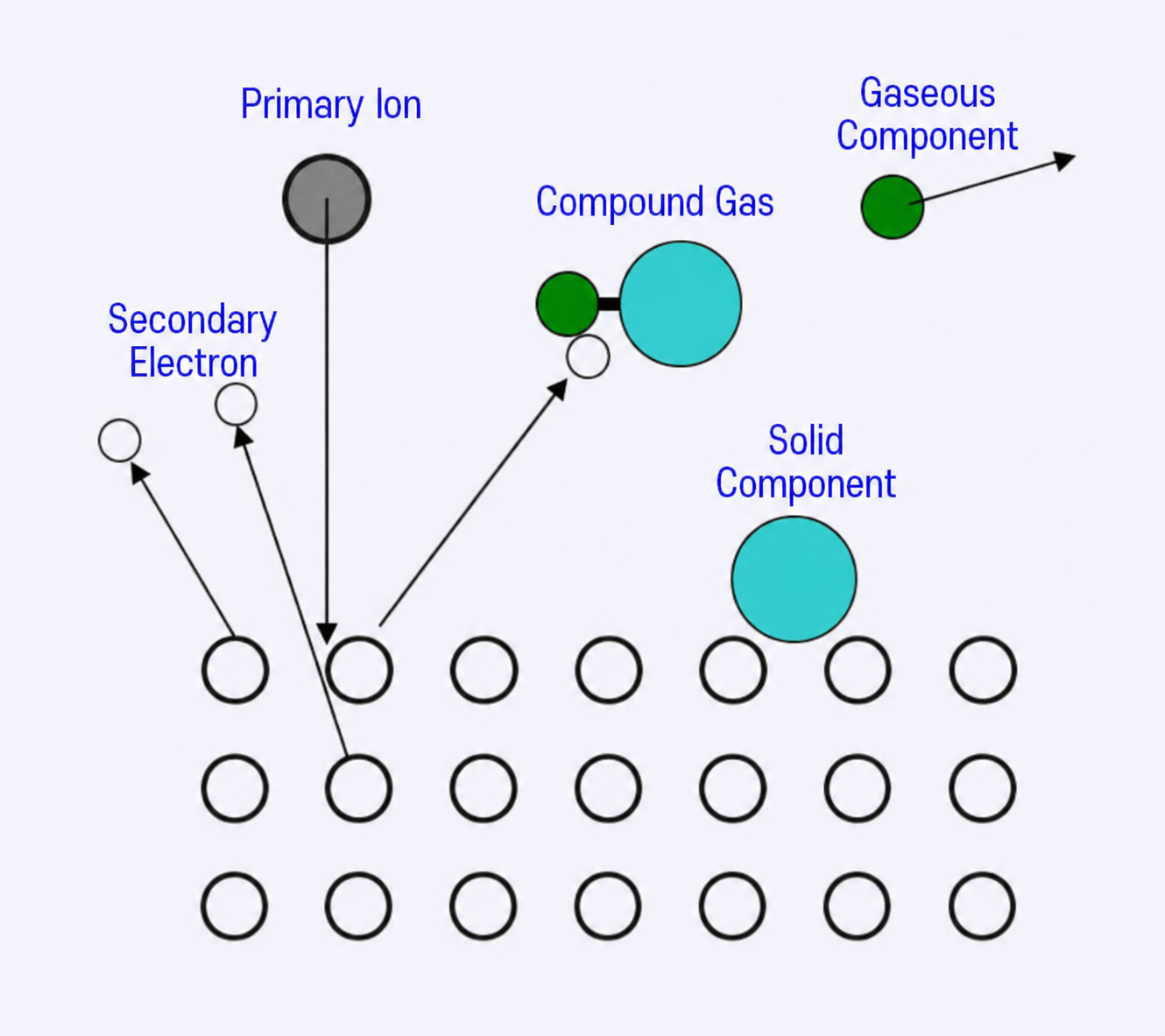
Figure 10 - Beam-Assisted Deposition Conceptual Diagram